Parking Battery-Power Station, 3X capacity and 3X cheaper than dedicated options + extra functionality

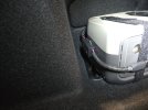
I've given up on the idea of an auto-switching relay because the camera just doesn't like any kind of power interruption and the EcoFlow won't output power until it senses a load, which causes an even longer power interruption. So, I went with the minimalist solution that GPak posted earlier in this thread. The EcoFlow is charged directly from the 12v utility output when the ignition is on, the EcoFlow directly powers the camera via USB, and the final USB plug also goes to the 12 utility outlet in the car with the USB adapter as the park/drive mode trigger. If the temps are outside of the operating range of the EcoFlow, I can just move the USB cord from the EcoFlow to the 12V utility outlet adapter to power the camera. In the image below, the wires are soldered together and covered with heat shrink. The resulting bundle is held out of the way with velcro strap that sticks to the trunk liner. Maybe I'll pick up a 90 degree USB adapter plug to keep the wire more out of the way.

I'm a little disappointed not to have the auto switching relay, but happy to have a nice large battery for parking mode recording!
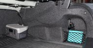
IMG_09333.JPG
 
Last edited:
I'm a little disappointed not to have the auto switching relay, but happy to have a nice large battery for parking mode recording!
Those relays are just too slow, they'd have to be able to switch in under 10ms like a ups.
 
I haven’t played much with my A229 Plus yet, but my first impression how it operates isn't very positive.
Compere to Mini 2, the A229 Plus is annoyingly slow, taking at list twice as much time to start recording.
It also takes longer to switch from normal recording to parking and vice versa.
It uses Super Capacitor, to properly close the video and shut down once the power is off.
Why doesn't that same Super Capacitor help to smooth out voltage ripples and brief (milliseconds) voltage interruptions?
May be it is not that “Super” anymore? :unsure:

Video shows how the Auto Transfer Switch works with Mini2, but doesn’t work with A229 Plus.
Hence A229 Plus will be powered through Power Station as originally, without decoupling.

 
Last edited:
GPak, what you are demonstrating with the A229 Plus power cycling due to the interruption in power is the same behavior that I saw with my A139 Pro. It would do a total reboot when power was interrupted. Adding the USB DC-DC converter to boost the voltage of the EcoFlow to match the Viofo USB utility outlet adapter helped switch INTO parking mode better, but not come OUT of parking mode. This was odd behavior given that the super cap should have "filled" in the brief time of the power gap, as you've already pointed out. The power sensing circuit in the camera must be located upstream from the cap, so it signals the camera to save its files and power down before the cap discharges itself when the power is actually cut. The power sensing feature just seems to be super sensitive. Perhaps this was a design choice intended to minimize the likelihood of losing a file due to power interruption.
 
For the last week the temps have been getting a bit warmer but also very sunny and the camera was warm to the touch, i was getting constant reboots on the a229 pro.
Measured the voltage output on the ecoflow and it was reading 4.9v, installed the xl6009 dc booster and set it to 5.3v and hope this fixes the reboot issue. Wattage went up 1w to 7w now when recording.

20240210_125922.jpg
 
Last edited:
Glad your voltage booster worked!

I spent some time playing around with my DC-DC converter (https://www.amazon.com/gp/B08HXR6KQB) today, but I made an unfortunate discovery. This particular DC-DC converter puts out a higher voltage until you put a load on the output. So, I used my power resistors that I showed a few posts ago and adjusted the output to about 5v2 with 1A2 load on the output. Without the load, however, the converter outputs about 12v. The Viofo A139 Pro sees the 12v signal and says "Nope, not gonna turn on." So, my DC-DC converter won't work in this application. Otherwise its a great little device... Oh well.

I did see another vendor that is selling the xl6009 dc booster, so perhaps I'll order a set. Looks like you get 10pcs for $9 here. @forcefed: Where did you get that great little plastic box to house the step-up board? I've looked for a few, but haven't found anything ventilated that is so nice and small.

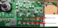
Another option (maybe a last resort?) is to open the EcoFlow unit and tweak the resistors that sets one of the 5v regulators and adjust it to something closer to 5v25. It is likely that one resistor or a pair of resistors sets the output level for each USB port. I found this image in a YouTube teardown of a River 2 unit. The board has all surface mount components, though, so I don't have the necessary tools for this kind of work right now. I'd have to look up the chip that they use and figure out which resistors set the output level.

River 2 USB Backside PCB Markup.jpg

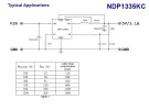
Below is screen cap from the voltage regulator used in the Viofo 12v to 5v converter box. This particular regulator chip is precisely intended for dashcam use as the table below the circuit shows several resistor combinations that provide voltage overhead that is intended to compensate for resistive loss in the cable run to the camera.

Viofo Voltage 5v Regulator Chip.jpg
 
Last edited:
Glad your voltage booster worked!

I spent some time playing around with my DC-DC converter (https://www.amazon.com/gp/B08HXR6KQB) today, but I made an unfortunate discovery. This particular DC-DC converter puts out a higher voltage until you put a load on the output. So, I used my power resistors that I showed a few posts ago and adjusted the output to about 5v2 with 1A2 load on the output. Without the load, however, the converter outputs about 12v. The Viofo A139 Pro sees the 12v signal and says "Nope, not gonna turn on." So, my DC-DC converter won't work in this application. Otherwise its a great little device... Oh well.

I did see another vendor that is selling the xl6009 dc booster, so perhaps I'll order a set. Looks like you get 10pcs for $9 here. @forcefed: Where did you get that great little plastic box to house the step-up board? I've looked for a few, but haven't found anything ventilated that is so nice and small.

Another option (maybe a last resort?) is to open the EcoFlow unit and tweak the resistors that sets one of the 5v regulators and adjust it to something closer to 5v25. It is likely that one resistor or a pair of resistors sets the output level for each USB port. I found this image in a YouTube teardown of a River 2 unit. The board has all surface mount components, though, so I don't have the necessary tools for this kind of work right now. I'd have to look up the chip that they use and figure out which resistors set the output level.


Below is screen cap from the voltage regulator used in the Viofo 12v to 5v converter box. This particular regulator chip is precisely intended for dashcam use as the table below the circuit shows several resistor combinations that provide voltage overhead that is intended to compensate for resistive loss in the cable run to the camera.
Yes amazon has those xl6009 boosters, there's also this kind https://www.amazon.com/gp/B09259SZJX but you only get one for the same price.
The box i 3d printed, plenty of designs on www.thingiverse.com
 
My USB-C voltmeter arrived today and I was able to measure the EcoFlow provided voltage at the camera end of the 10ft cable. It seems to average about 4v6 with a 1A2 current draw, but both fluctuate up and down a bit. I'm wondering if this a symptom of the internal super cap trying to keep up with the power demands of the camera? I'm guessing that it's operating on the cusp of voltage starvation at this point. It would likely be nicer to give the camera a more steady 5v power supply.

I'm also thinking a quick experiment might be to add a cap to the output side of the DC-DC convertre that I already have - maybe charging the cap will be enough of a load on the board to keep the output from soaring to 12v before the camera starts...
 
Adding a 220uF output cap to my DC-DC converter didn't do anything to help reduce the voltage and allow my dashcam start up. Further adding a 220uF input cap prevented the DC-DC converter from functioning at all. So much for that idea...
 
For the last week the temps have been getting a bit warmer but also very sunny and the camera was warm to the touch, i was getting constant reboots on the a229 pro.
Measured the voltage output on the ecoflow and it was reading 4.9v, installed the xl6009 dc booster and set it to 5.3v and hope this fixes the reboot issue. Wattage went up 1w to 7w now when recording..
So far so good, had some really sunny days recently and haven't had any reboots at all when i set it to 5.3volts at the ecoflow. I have a usb c passthrough voltage tester coming in soon and will check the voltage drop at the camera eventually.
 
Good to hear!

I was hoping the voltage booster would solve your power cycling issue. From what I was able to measure with an inline USB meter, the 10 foot 20ga Viofo cable drops about 0v25. Pretty sure this is why the Viofo USB adapter puts out 5v25, so by the time power gets to the camera, it is still at 5v00. Setting your booster to 5v3 likely delivers 5v05 to the camera.

Making your own 18ga wire will “conserve” another 0v10 over a 10ft run.
 
Hello everyone! This is my first post, although I am following the forum for a while. My first cam was a 70mai A800, 2ch and I was very happy with its performance, except the parking mode (only starting few seconds after G sensor activation). Since last month I got a new car, Mini Countryman, and decided to upgrade as well the dashcam to Viofo A139 Pro 2ch. Now things got complicated, as there is too much electronics in the new car and adding a ~5,5 Wh consumer might kill the car's battery fast. I actually measured the battery voltage after 2 days of parking and is around 11.9 - 12.1 V. With a Diesel engine and this low voltage, hardwiring the dashcam already will certainly not help. So I started to dig up into this and other forums for a solution.

Thanks GPak for starting this thread and to all who contributed here, it helped me to think a solution for my needs. Few of the things I am looking to into:
  • I am not into power stations, as there is too much stuff and many functions/over-protections that I don't need, so I want to keep things as simple as possible.
  • Up to 5 days of parking mode: I often leave my car in airport parking for 3 - 4 days, when travelling abroad. Around 500 Wh looks to be the sweet spot.
  • Compact and unobtrusive / integrated: after I will have a working solution, I will have make it compact and fix it under the dashboard - front of passenger seat (close to the fuse box).
  • Set it and forget that is there: it has to function automatically, so not to plug/unplug or trigger switches manually.
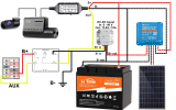
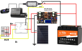
  • For the moment, I went with the 12V/50A LiFePO4 in the below diagram is the solution, but if the solution is viable, I am looking into have a custom cell arrangement (for a better fit) and a better BMS (the one in this battery is lacking cold temperature cut-out). I am not even convinced about the cold-cut, as the charging should start only when I start the car & heating and a well insulated battery should stay kind of warm from the ~0.5 A discharging current.
  • For charging I think that the booster at 10A should do the trick, as most of my travels are minimum 2 hours.
  • Later on, for those long airport parking days, I am considering adding a rooftop solar panel (dashed lines in the diagram).
I will need your opinion if the components and connections are ok in this setup.

Many thanks!

DashCam-ParkingMode-Batt-HardWire.pngG
 
So far so good, had some really sunny days recently and haven't had any reboots at all when i set it to 5.3volts at the ecoflow. I have a usb c passthrough voltage tester coming in soon and will check the voltage drop at the camera eventually.
I am glad it worked.
Most if not all consumer grade Super Capacitors (SC) are rated to 2.7V max, hence inside DVR two of these in series will be 5.4V max, however SC can work with lower voltages up to some point.
I am sure DVR also has some kind of under and over voltage protection circuitry, which cuts the power outside of certain range, say 4.6-5.4V.
4K DVRs require more power i.e bigger (capacity-wise) SC, but bigger SC requires more time for initial charging, I guess that is why these DVRs are taking about twice as much time to boot, compere to Mini2.
So SC size/capacity is compromise, probably cutting the margins on both ends.
 
Last edited:
I will need your opinion if the components and connections are ok in this setup.
Leaving the solar part aside for now, the DC side diagram looks fine, except DC-DC Boost converter can not be used to charge the Battery.
You need to replace it with DC-DC charger.
-First, the Boost converter requires some voltage differential between input and output (input should be lower).
Car's smart alternator can provide up to 14.5V and that is higher then 13.8V boost converter on diagram
I am also not sure why 13.8V?, 12V LFP Battery usually requires 14.4V to be fully charged.
-Second, the Boost converter, although rated at 10A, will not limit current to 10A (that is major difference between Converter and Charger).
The amperage would be whatever Battery will accept, it could be much higher than 10A.
Standard chargers for 12V LFP Battery are widely available, some include dual DC and Solar charging capability.
You can also use automatic Buck-Boost Converter with adjustable constant current, constant voltage (CC-CV) as a charger.

I am currently testing LTO Battery (DIY), basically the same concept, it does not really matter LTO or LFP, check it out here:
 
Last edited:
DC-DC Boost converter can not be used to charge the Battery. You need to replace it with DC-DC charger.
-First, the Boost converter requires some voltage differential between input and output (input should be lower).
Sorry for not being specific, is a buck-boost (step-up/down) DC-DC converter, taking input from 8V to 40V and regulating at 13.8V.
I am also not sure why 13.8V?, 12V LFP Battery usually requires 14.4V to be fully charged.
According to few sources (What is the best MAX charge voltage for LiFePo4? & Charging LiFePo4 to 3.4V and 3.5V with and without Absorption), a voltage of 3.4V - 3.45V/cell is charging the battery (over a longer absorption time) at the same capacity as 3.65V, but with less stress for the battery (longer lifetime). For me even a 90% capacity will be alright.
...although rated at 10A, will not limit current to 10A (that is major difference between Converter and Charger).
You are right, it does not have current regulation / CC. I should probably use a boost converter and feed about 19V to the PV connector of the Victron MPPT 75/15

You can also use automatic Buck-Boost Converter with adjustable constant current, constant voltage (CC-CV) as a charger.
I was looking at the one you posted in the LTO topic, and ordered on Amazon Germany (2-3 weeks delivery). It can replace both the boost converter and the Victron MPPT, so probably is the best route. I updated the schematics to this one. DashCam-ParkingMode-Batt-HardWire_BB-CC.png

I am currently testing LTO Battery (DIY), basically the same concept, it does not really matter LTO or LFP, check it out here
I am also following that topic, I thought to let it be LTO specific. I will actually address there few questions related to components.

Thanks!
 
I left out solar part in the previous post because it is not that simple for the DIY project.
I don't think, you can directly mix solar and car DC system, because Solar panels can provide higher voltage, usually so called "12V panel" open voltage can be as high as 24V, and optimal MPPT voltage is usually around 17V.
There are special dual input DC+Solar chargers automatically prioritizing input.
Here is an example of dual charger on amazon, others are also available.
https://www.amazon.com/gp/B0BZCXNHDV
https://www.amazon.com/gp/B08X6HH5GW

The Buck-Boost charger on the diagram works well as DC-DC charger, and I am sure, it will work well as a Solar charger, but you cannot use it for both at the same time.
For DC-DC MPPT is not needed, so I briefly tested it and found optimal MPPT setting to be about 0.2V below the car's minimum charging voltage under the load (I set it to 12.3-12.5V, with my power supply charging voltage at 12.6-12.7V) that is optimal and it works at about 90-92% efficiency, similar to all other chargers.
Any deviation from that optimum in MPPT setting for DC-DC, will drop the output amperage, if you set it too high, or charger gets really hot and inefficient if you set it too low.
For the Solar panel, you will most likely need to set MPPT to about 17V.
 
Last edited:
So basicaly is there a way to trick the dash cam into doing parking mode without hardwiring? I have a bluetti ev3a and viofo a229 plus duo
 
So basicaly is there a way to trick the dash cam into doing parking mode without hardwiring? I have a bluetti ev3a and viofo a229 plus duo
If you leave it recording for 5 minutes without movement it should enter parking mode, but for me it didn't always do this.
 
If you leave it recording for 5 minutes without movement it should enter parking mode, but for me it didn't always do this.
How do you do that, do you mean I have to plug the bluetti into the car’s 12v socket?
 
Back
Top